
A complete guide to swapping an LS Camshaft at home in your garage – one of the easiest ways to unlock hidden horsepower
Words: Marcus Gibson Photos: Strong Style Photo
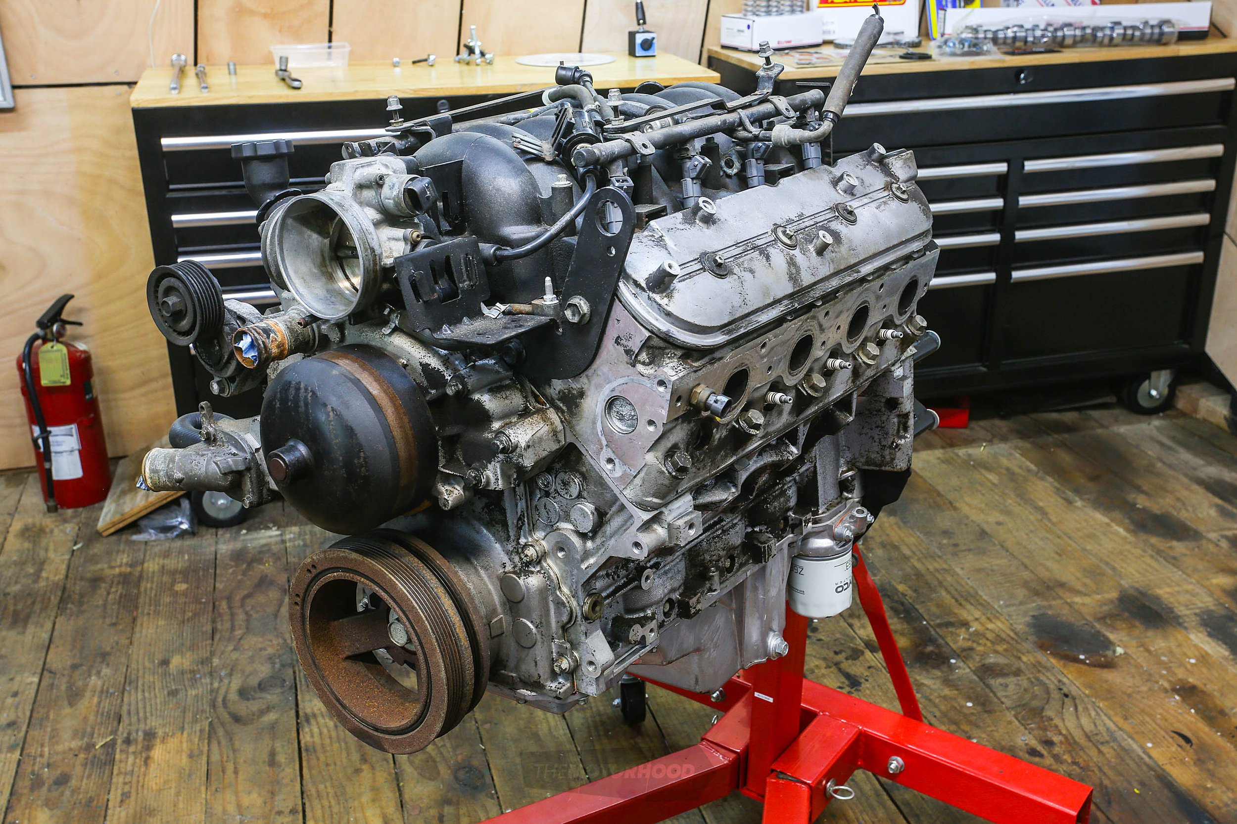
It’s no secret that the GMs LS-based small blocks are great performing engines that are super reliable. As far as an out the crate, or junkyard, option is concerned, they are hard to beat for bang for buck. However, there is always room for improvement; improvements that won’t break the bank but will unlock a few extra ponies hidden within — all without the need to remove the heads. While the normal swag of bolt-ons will net you a nice little gain, a cam swap is really going to awaken the beast within. We’ve teamed up with Kelford Cams and will be using one of their CNC ground bump sticks for the example.
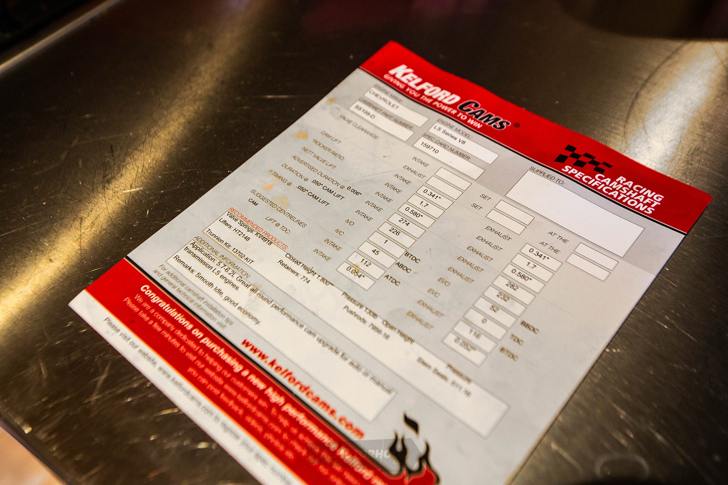
Deciding on the perfect cam for your application can be a little tricky, and it’s not something we’re going to get into here, as it is a whole topic on its own. Instead, we recommend you speak to the experts in making your decision — that’s what we did. For our otherwise stock LS1 that is going to be slotted into a cruiser with an auto and stock converter, we opted for the Kelford 108-D, which is by no means their wildest profile but shouldn’t give us any dramas with the likes of vacuum. But, as we said, talk to the experts. The team at Kelford will be happy to assist you in making your decision.
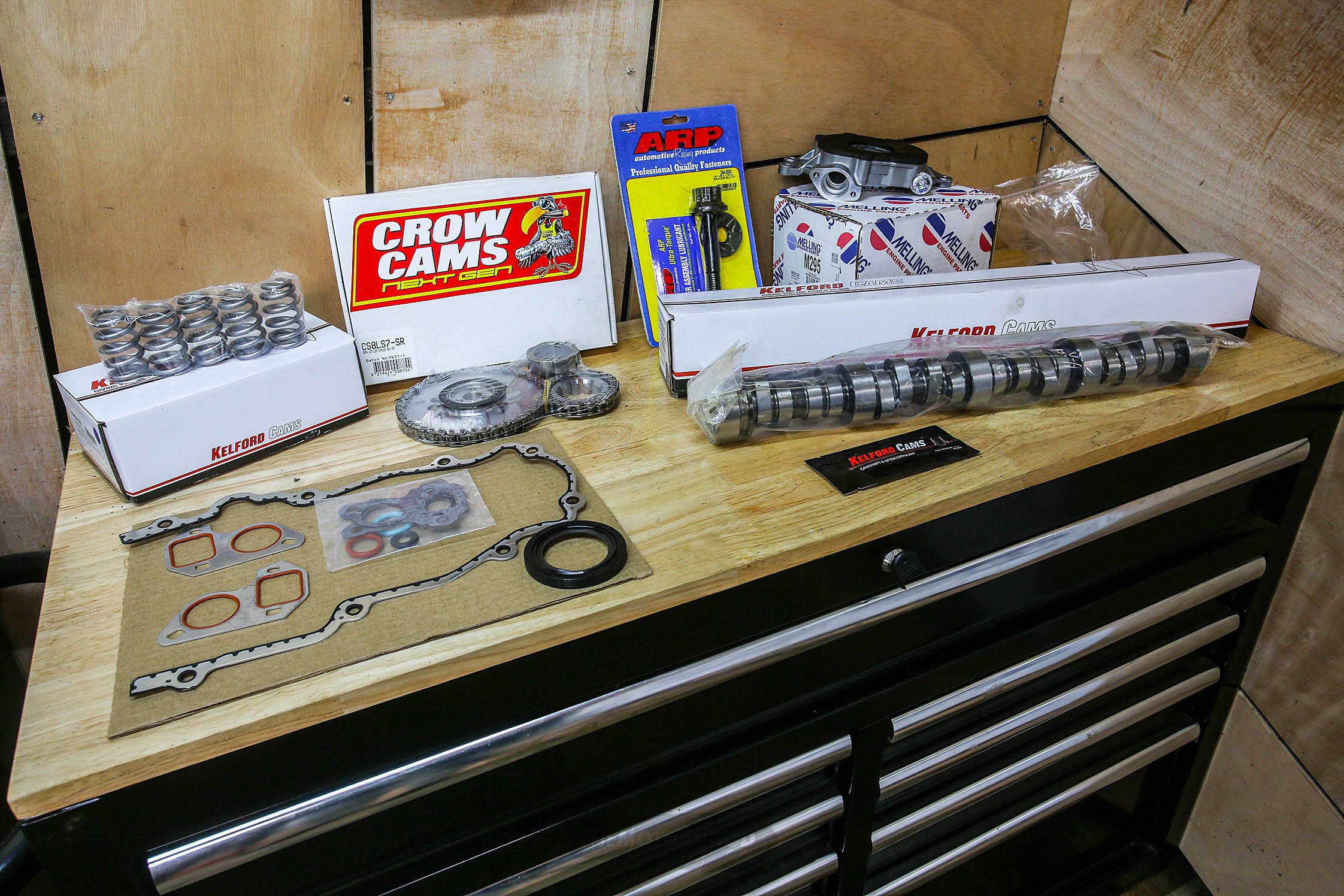
What you’ll need
Along with swapping in the cam there are a few other items you’ll want to replace at the same time. Some are simply preventative maintenance if you’re using an unknown donor motor like us; others, like the valve springs, are to suit the new cam. Your cam card will list the supporting modifications required; in Kelford’s case, it even includes the part numbers, which makes it easier. Kelford supplied us with almost everything we needed, which further simplified the process.
Step 1
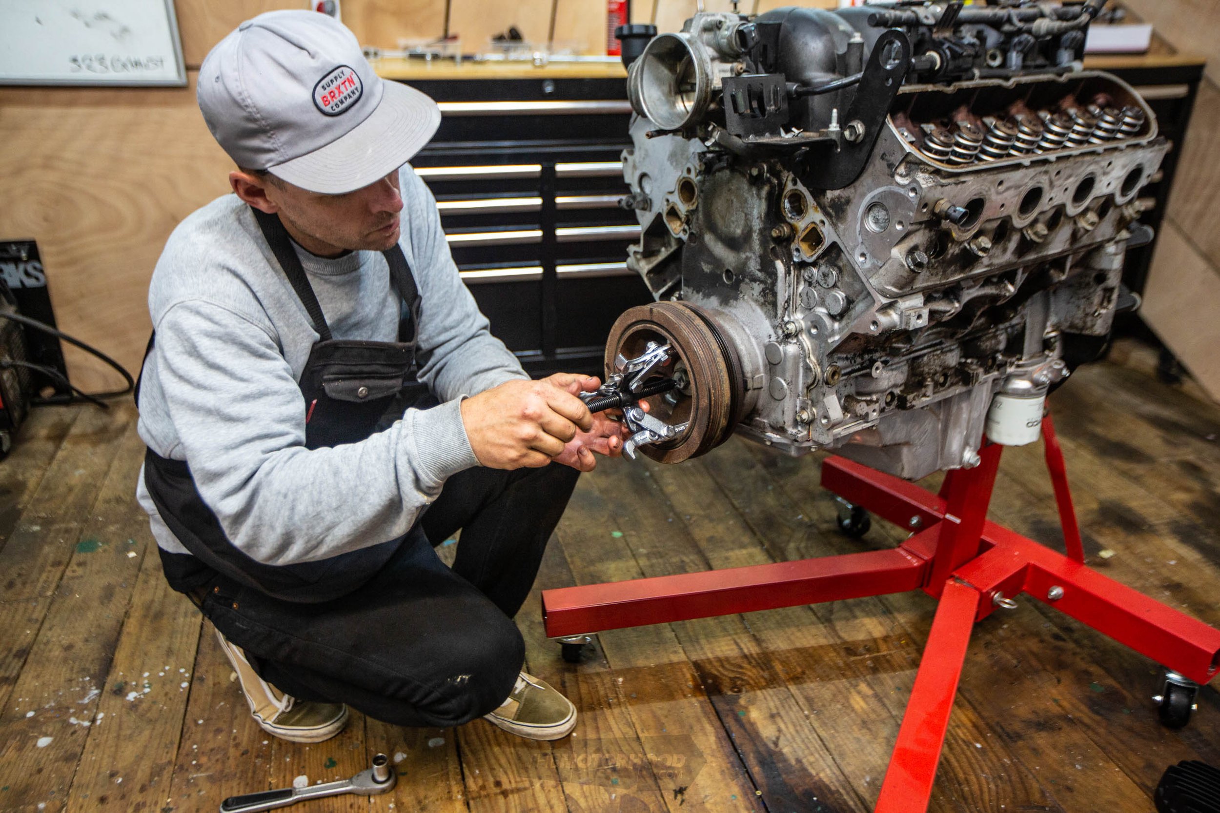
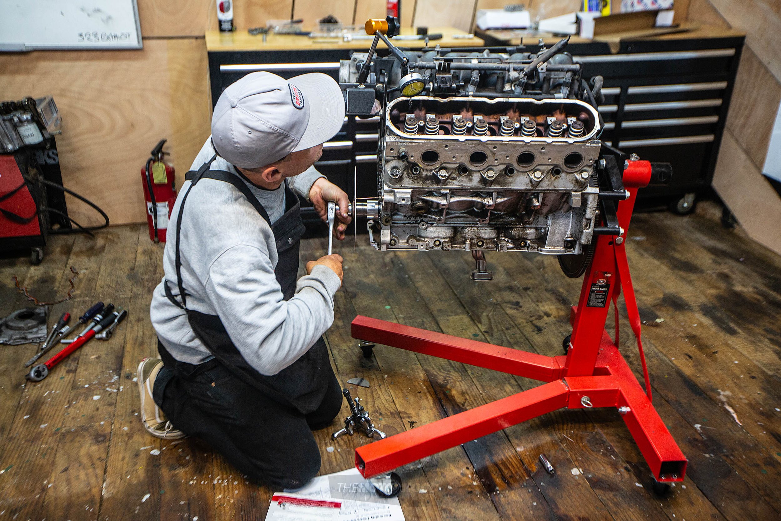
We have the luxury of the engine being mounted on a stand, although this project is completely achievable with your engine still in the car; it will just require the removal of anything in front of the engine to give you room to remove and install the cam. In stock applications like a Commodore or Camaro, this means the radiator and any other coolers and hoses.
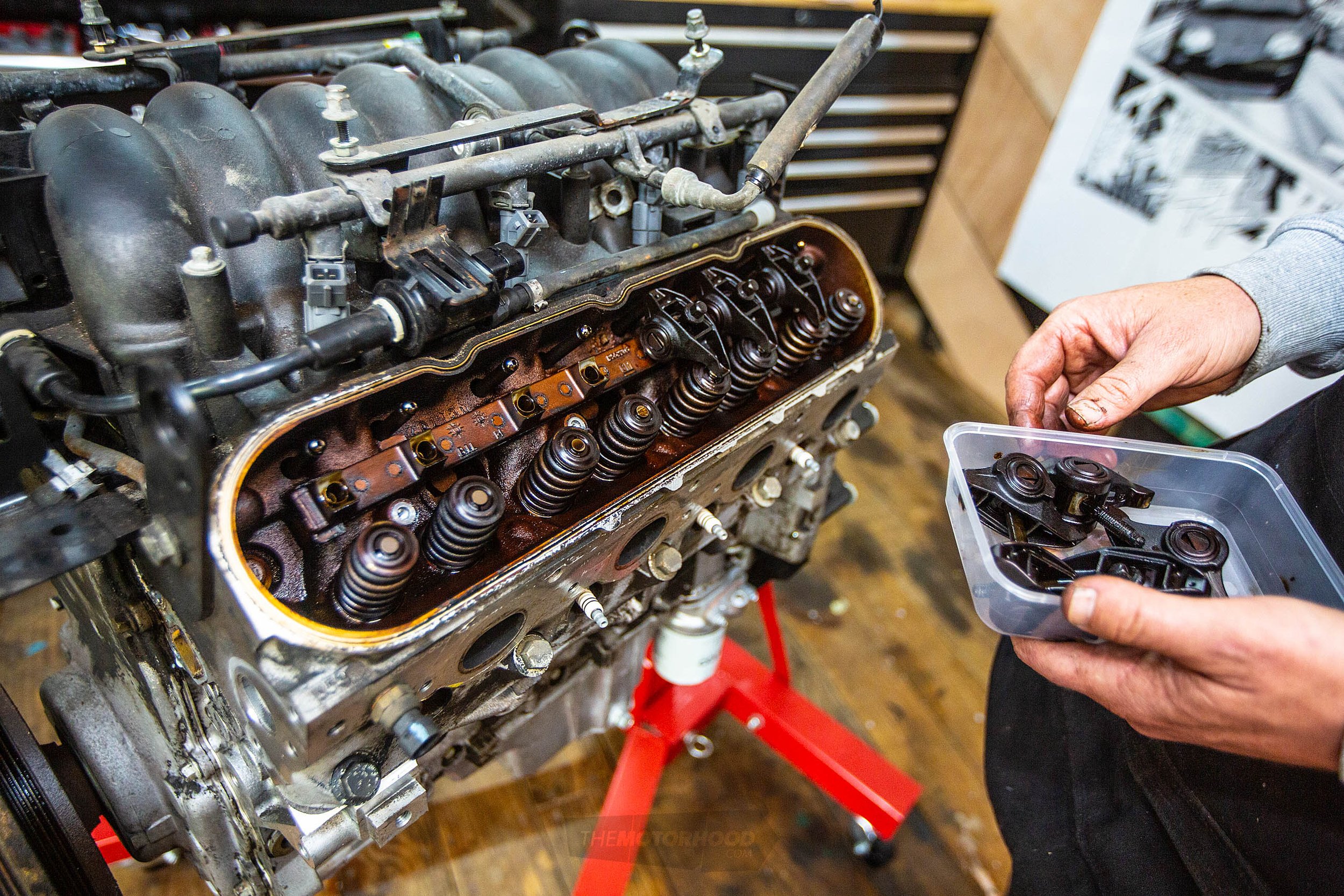
Step 2
The second step is to remove the rocker gear. Each cam cover is held in place by 4x8mm bolts. Once you have the cam covers off, you can loosen the rocker studs. Do so to any that are not under load — it will be six of the eight rockers on each side. Loosen these, and then rotate the motor until your remaining rockers are unloaded. Once these are loose, you can pull the complete set from each side of the motor as one unit. Remove the pushrods and spark plugs also.
Focus now shifts to the front of the engine. Remove the water pump assembly held in place by 6x10mm bolts. Keep the gaskets if they are in good condition — although we’ve decided to replace everything while the engine is apart, which we’d recommend if you’re dealing with a used engine as we are.
Step 3
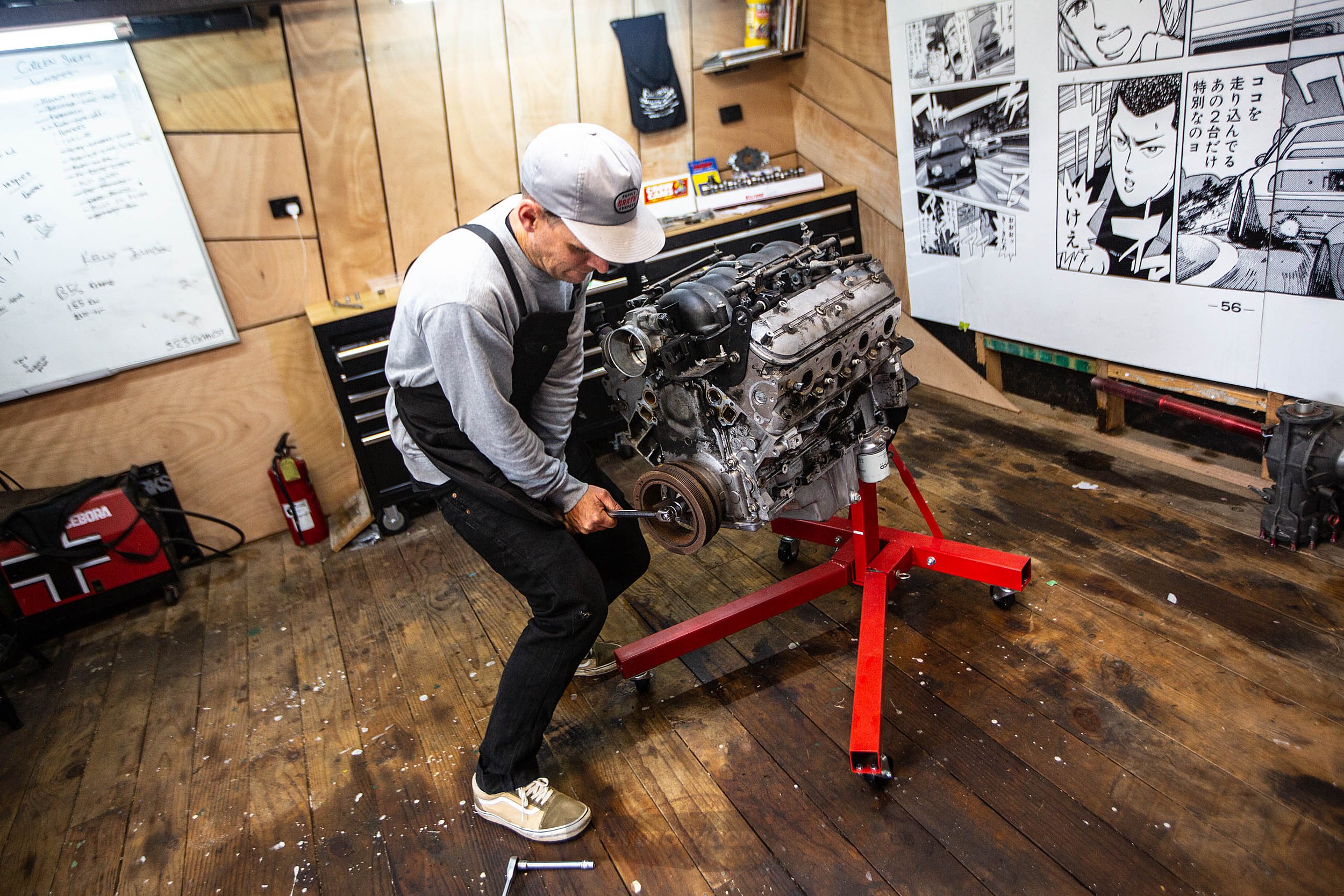
The next part to remove is the balancer. For this you will need a three-jaw puller. You can purchase a specific LS kit online that has the extended dowel, as the seat is deep inside the crank. However, we opted to do it another way, with a shorter dowel and factory bolt. Once you’ve cracked the crank bolt, wind it out a few turns. Place your three-jaw puller — we used a 100mm three-jaw — onto the pulley, which will press onto the head of the bolt. Tighten the puller until the balancer touches the head. Loosen the bolt a few more turns, and repeat. It’s a little clunky to do it this way, but it removes the need to order a specialist tool. Full disclosure: we had to give the pulley a few gentle taps with a mallet once the bolt ran out of thread.
Step 4
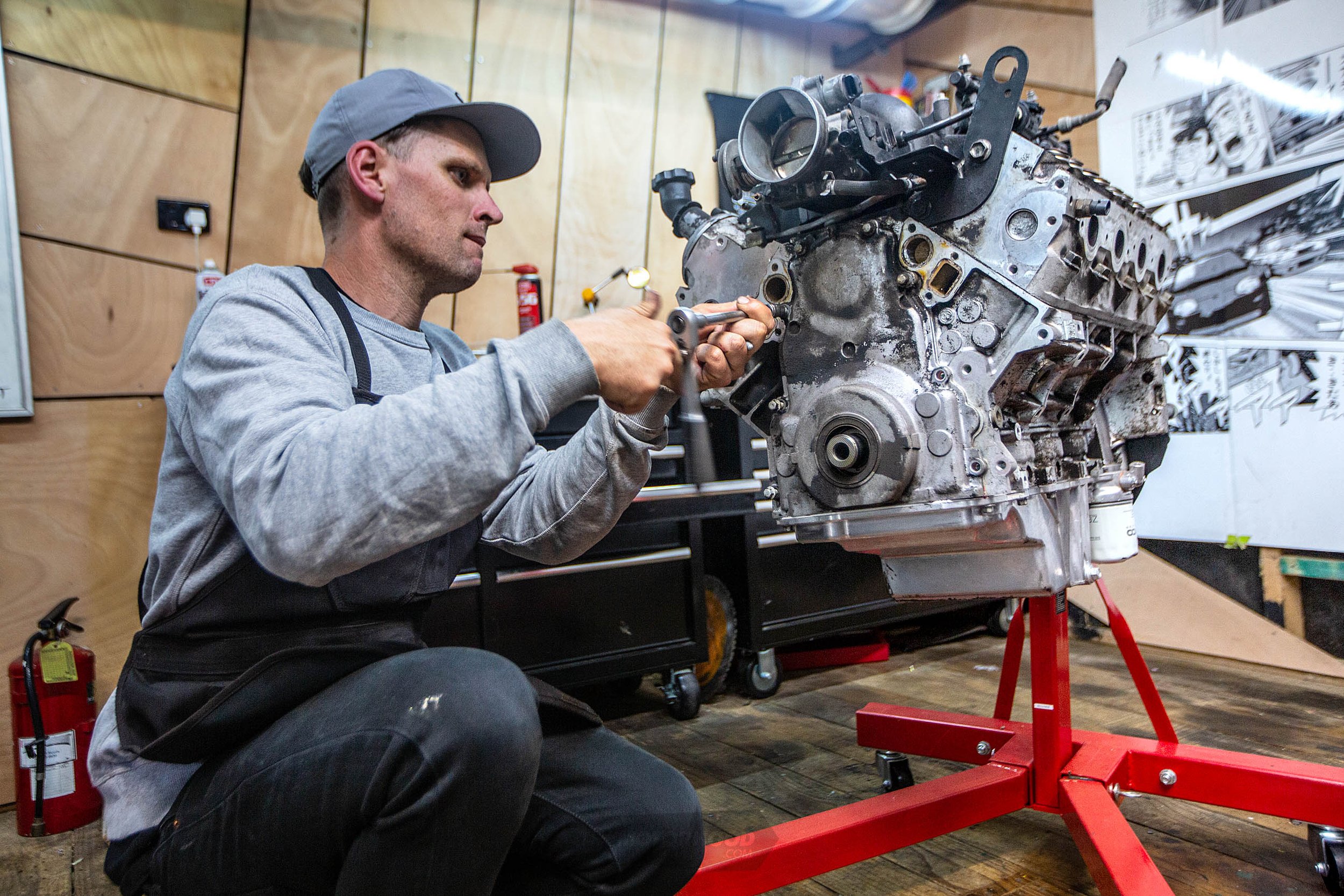
The front cover comes next. Remove the 10x10mm bolts, two of which are on the sump. This exposes the timing gear, oil pump, and cam sprocket. It’s important to note you do not need to remove the oil pump, and, in fact, if you’re doing it in your car, this will be difficult as you need to remove the sump to do so. As our example is an old engine, we’re replacing the pump as a little insurance.
Step 5
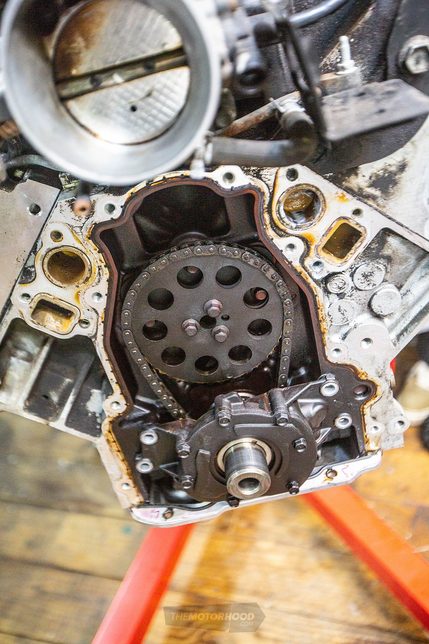
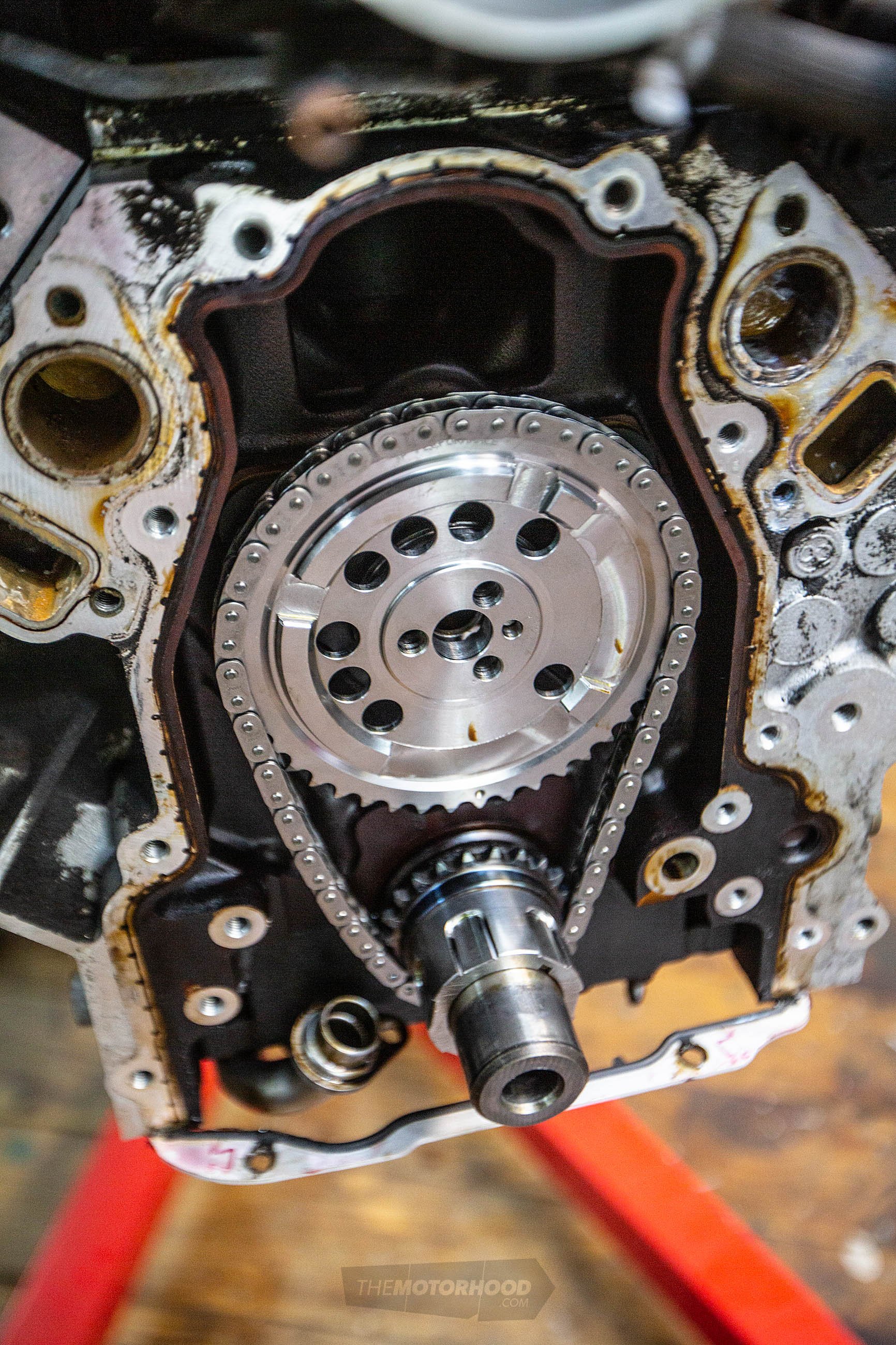
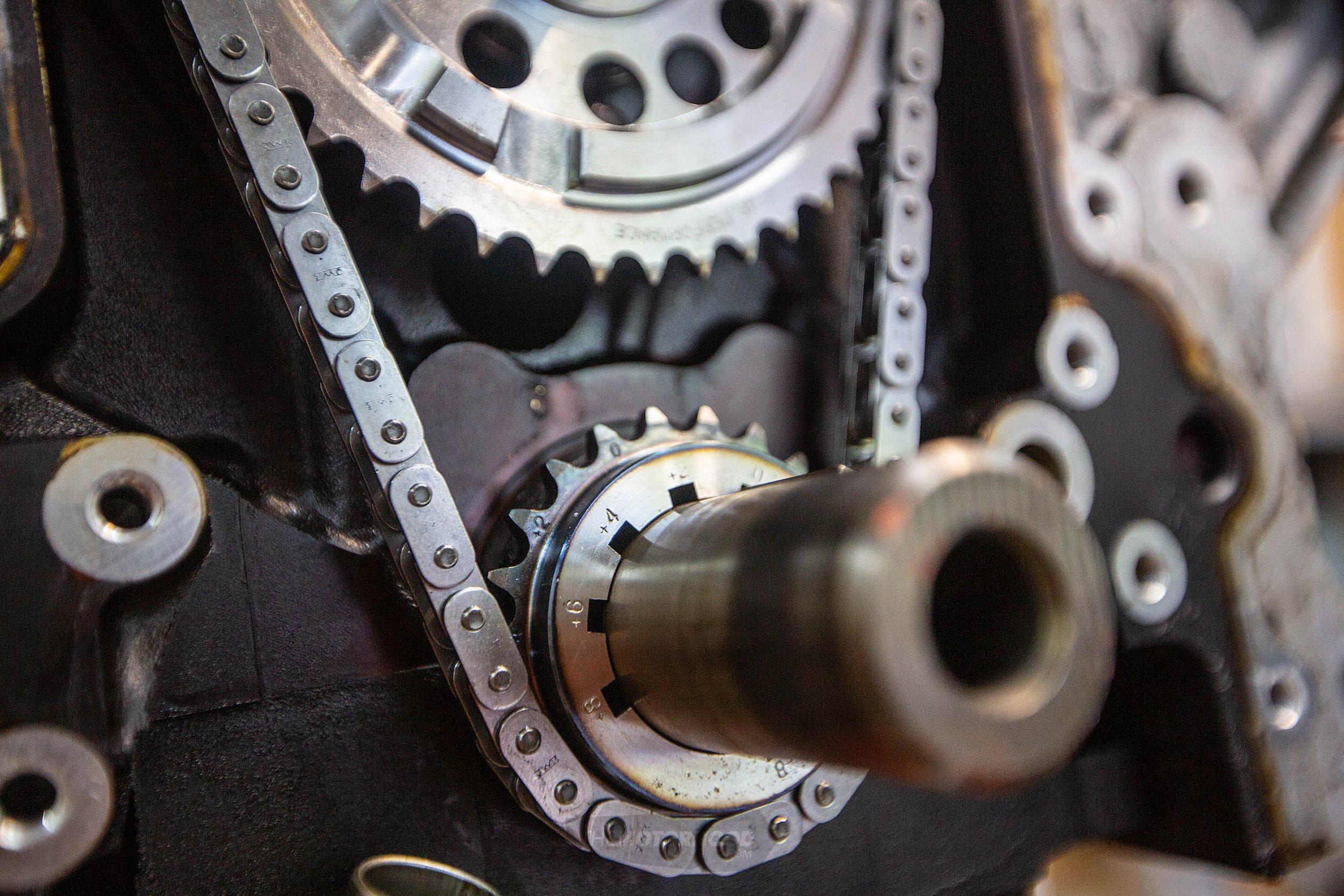
Before you go ripping out the cam, you’ll want to do things. First rotate the engine until the timing mark of both cam and crank line up — cam at 6 and crank at 12. It can be a little difficult to see the lower mark with the oil pump on, but not impossible. Once they are aligned, you can remove the cam sprocket — three 10mm bolts. This will reveal the retention plate, which is secured by four T40 Torx bolts. Remove these, too.
Step 6
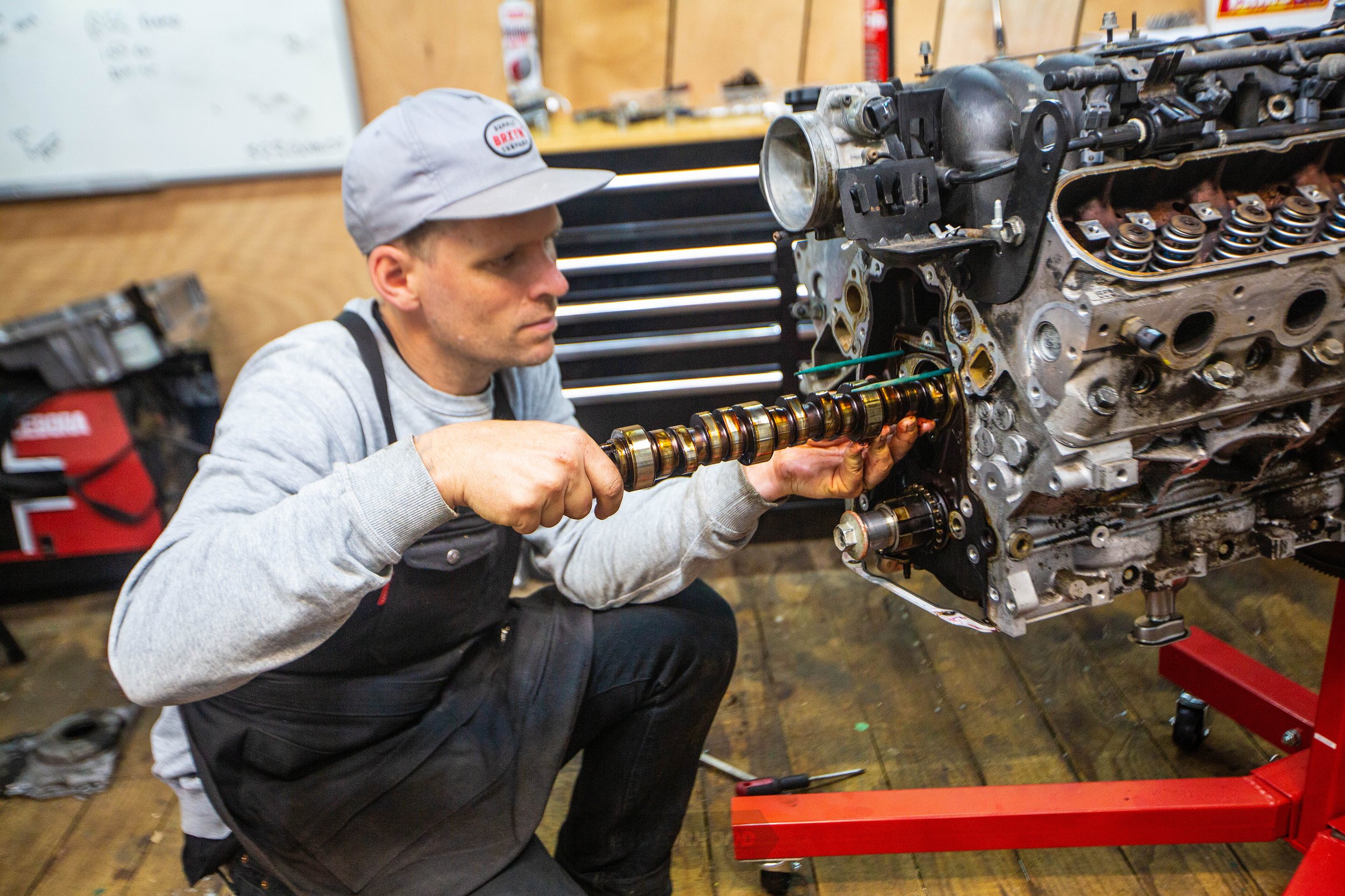
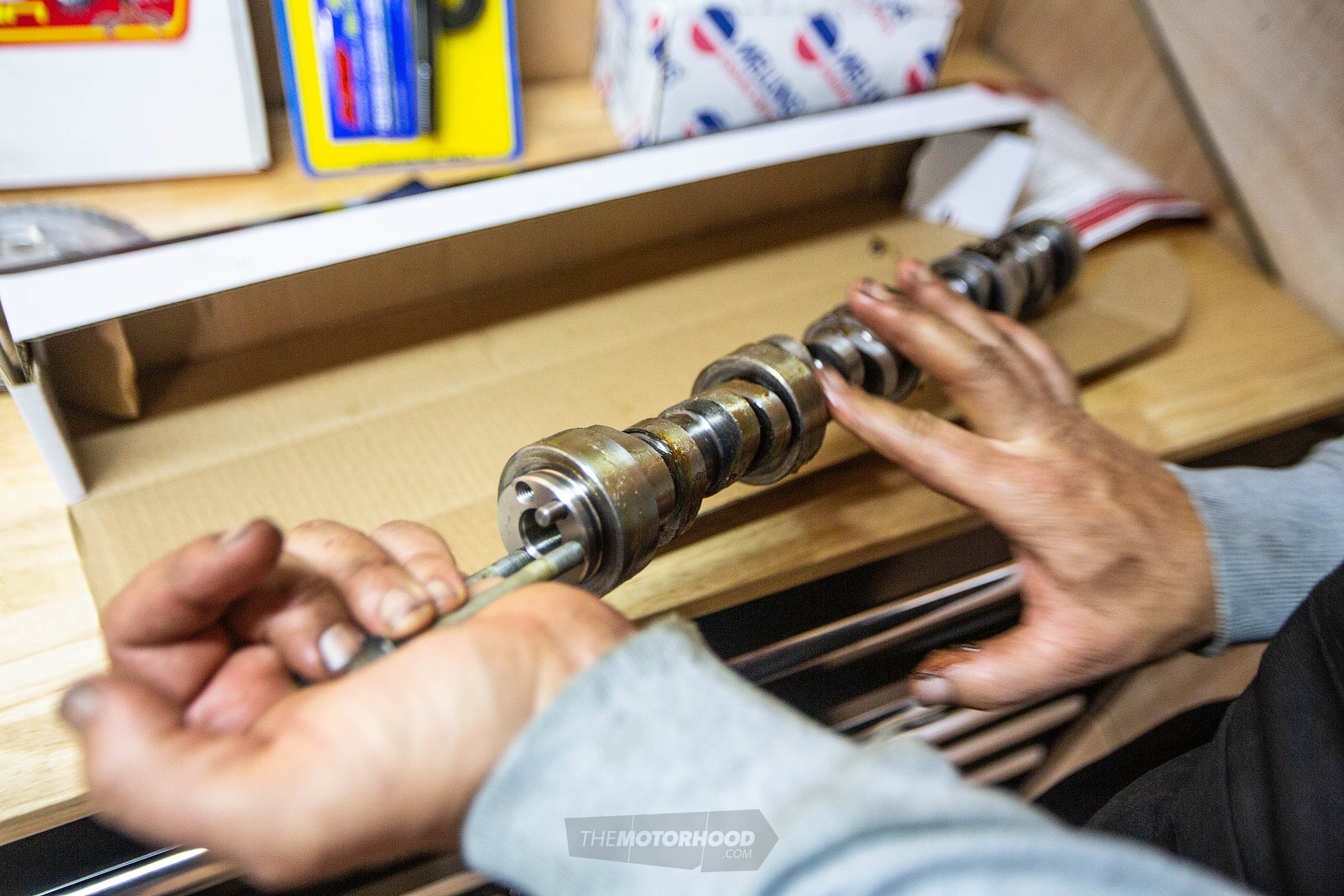
You’re now ready to remove the cam itself, although first you’ll want to spin the cam a few times, as that pushes the lifters up into the buckets. While in most good-condition engines this will be enough to hold them up while you swap cams, as a fail-safe you can insert two ⁵/₁₆ rods into the oil gallery holes, which are located either side of the cam. We used two clean garden stakes. They should slide the length of the engine and stop the lifters from falling into the sump and requiring the heads to be removed to reinstall. Now, carefully slide the cam out. To get a better grip on the cam, we used two water pump bolts as they are the same thread. Slide it out as straight as possible. You’re now ready to slot in the new cam.
Step 7
Kelford supplies its cams with assembly lube, which should be liberally applied to all the wear surfaces of the cam, but first you want to make sure you give it a clean just to be on the safe side. The cam should slot in there without any force required. Be as gentle as possible. Once it’s in, you can remove your rods and begin reassembly.
Step 8
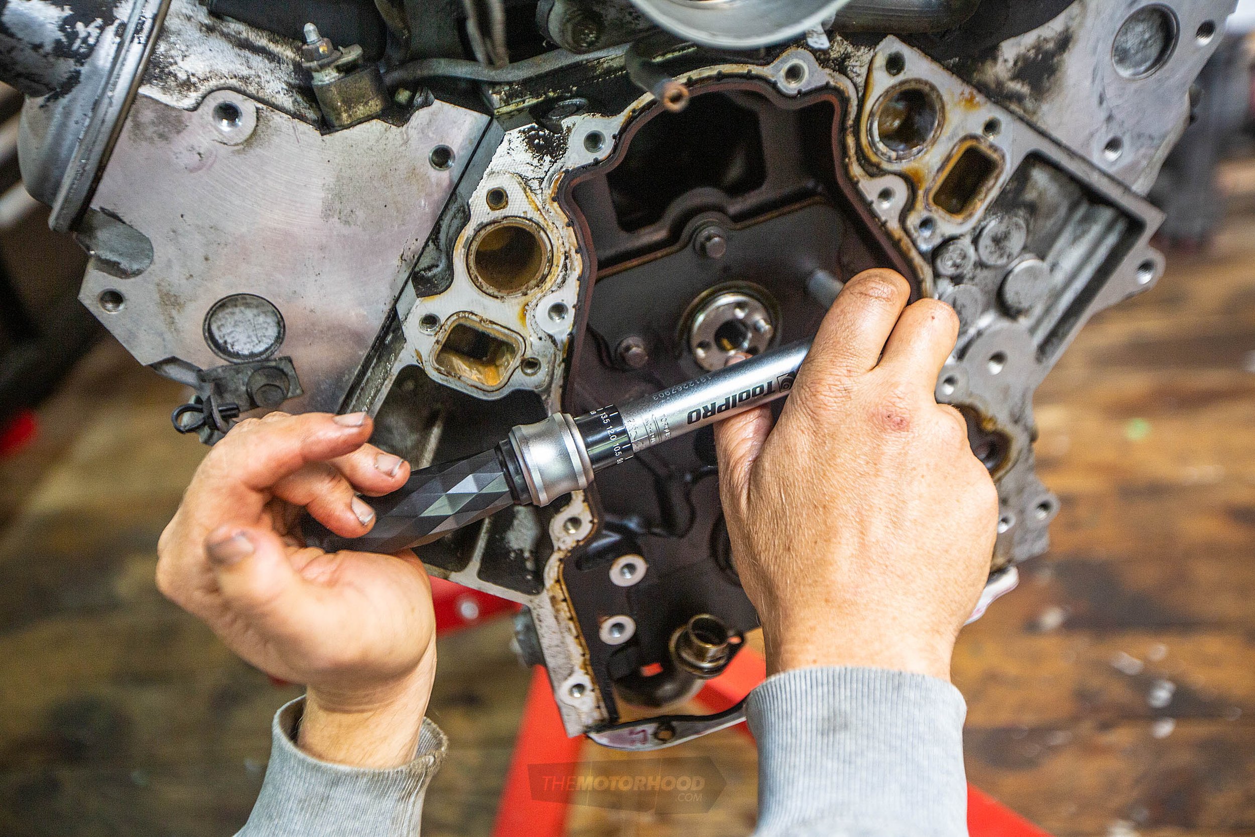
Install the retainer plate — gasket first. The torque setting for the four T40 Torx is 18 foot-pounds. Next, on goes the timing gear. We’ve opted to replace ours completely with an adjustable set from Crower, which Kelford supplied. We opted to go single row to avoid the need to machine the timing cover as needed if you go double row. We are not building a race engine here. This set has timing adjustment on the crank sprocket, but more on that later. For now, we’re just going to set it up at zero and align both pulleys like we did before.
Step 9
Having the locating pin at 3 o’clock on the cam should see you right when sliding the timing set on. The other way to do it is to install the sprockets without the chain, get it aligned, and then remove the cam sprocket, install the chain, and then reinstall the sprocket with only finger tight bolts for now.
At this stage you have two choices, either to dial in the cam, which we’d recommend you do, or to simply bolt it together and cross your fingers it’s right and you’re not robbing yourself of power — or, worse, going to bend valves on start-up. For an extra 10 mins or so, it’s effort we’d say is worth doing, but your choice.
Step 10
Dialling in a cam with the heads on is a little more complicated than with the heads off, but we can check both the intake and exhaust valve opening points at .050-inch as shown on the cam card supplied with the cam. The reason is that there is no way to accurately push the lifter back down against the lobe once it reaches max lift, which rules out being able to check any other points of reference the cam card gives us.
Step 11
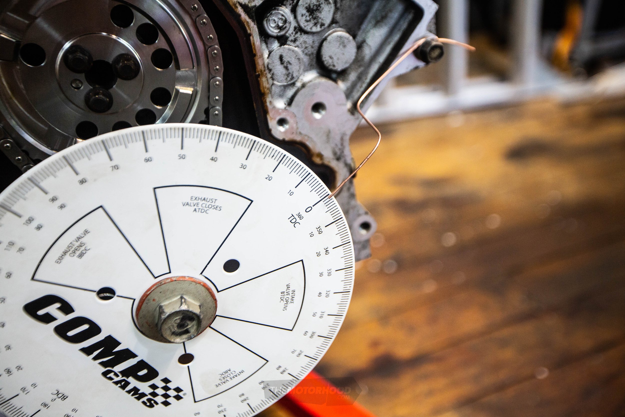
Top dead centre (TDC) for piston one needs to be confirmed. To do this we made a small tool, as shown in the pull-out box: “Making a TDC finder”. With your degree wheel mounted — we set ours so TDC was at about 1 o’clock — and a small piece of welding wire attached to the block and pointing at TDC on the wheel, back the engine off a little and then rotate it clockwise until it hits the stop. Record the measurement and then rotate it anticlockwise until it hits the stop. Record this measurement. Adjust the pointer to average out the two readings until you achieve the same number of degrees before and after TDC rotating each way. For example, if you get 10 degrees clockwise and 8 degrees anticlockwise, then shifting the pointer to 9 should give you the same reading no matter the direction you travel towards TDC.
Step 12
Next, you’ll need to set up the dial indicator and magnetic stand. Given that the LS1 engine is all alloy, finding a spot to mount can be difficult. We mounted ours on the existing factory lift hook. Bolting a plate to the cylinder head is another option. Placing a pushrod in both the intake and exhaust on piston one, set up the dial indicator on the intake pushrod first, ensuring it is perfectly aligned.
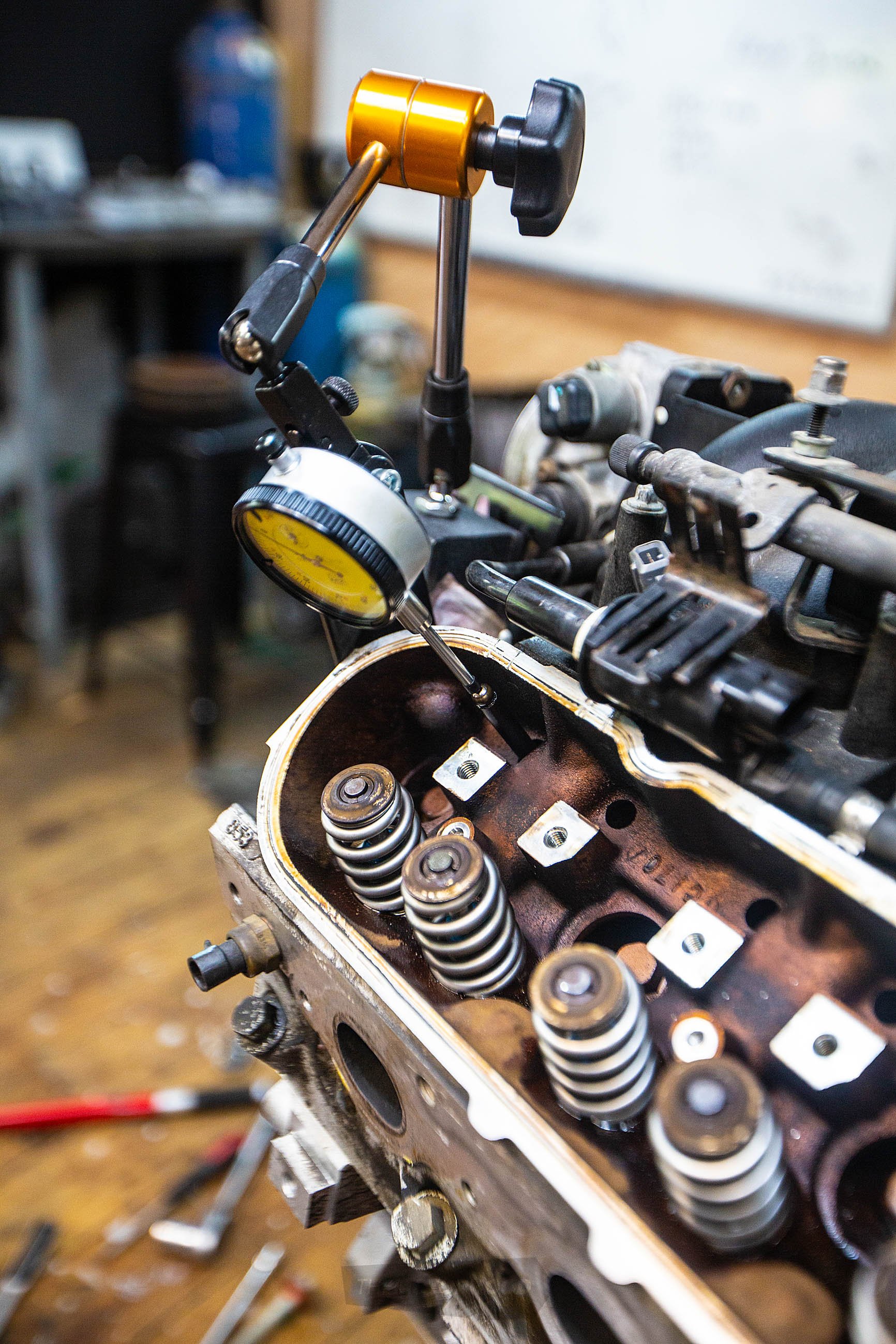
Step 13
You’ll now need to rotate the engine until you are on the base circle of the cam, at which point you set your dial indicator to zero. Our cam card states the intake valve opening point to be at 1 degree before top dead centre (BTDC) and the exhaust at 52 degrees before bottom dead centre (BBDC). It’s these numbers we’re trying to achieve on our degree wheel. When you’re coming up to near TDC, stop when the dial indicator shows .050-inch. Make a note of the reading shown on the degree wheel. It should be 1 degree BTDC. If it isn’t, don’t stress — we’ll deal with that later.
Now, set up the dial indicator on the exhaust pushrod and repeat the process of zeroing at the base of the cam and then rotating the engine until you reach .050-inch before on the exhaust opening. Now, in a perfect world these two numbers shown will match what the cam card showed. But say they’re both 2 degrees before, that would mean the cam is advanced 2 degrees, and, likewise, if it didn’t reach .050-inch till 6 degrees after our advertised figures, it would mean the cam is retarded by 6 degrees.
Step 14
So, what can be done to correct this? In our case we would simply remove the crank sprocket and shift the number of degrees advanced or retarded required to bring it back to zero. Our Crow Cam sprocket has adjustments in 2-degree increments. Just note: with this type of adjustment the number you shift on the keyway has to correspond to the number on the outside that you’d align to the cam sprocket dot. Therefore, if you have to advance it 2 degrees, you align the crank keyway to the +2 and the +2 on the outside becomes your new timing mark.
Once you have made the adjustment, you need to repeat the entire process to confirm your adjustment was correct. If so, then you can lock tight the cam bolts and torque to 26 foot-pounds. Install your oil pump if you’ve changed it, as we did, followed by the timing cover. Before tightening the bolts, slide the balancer back on so it will align the seal before torquing the bolts to the factory 18 foot-pounds.
Step 15
In order to get the balancer bolted down, you will need a longer than factory bolt to get it started — there are special tools. Once it’s started, use your old crank bolt and torque to 240 foot-pounds then remove the old bolt and replace it with a new one. We went with an ARP item. This should be torqued to 37 foot-pounds, and then rotated an additional 140 degrees.
When reinstalling the water pump, the bolts are torqued in two stages: first 11 foot-pounds, and then a second round at 22 foot-pounds.
Step 16
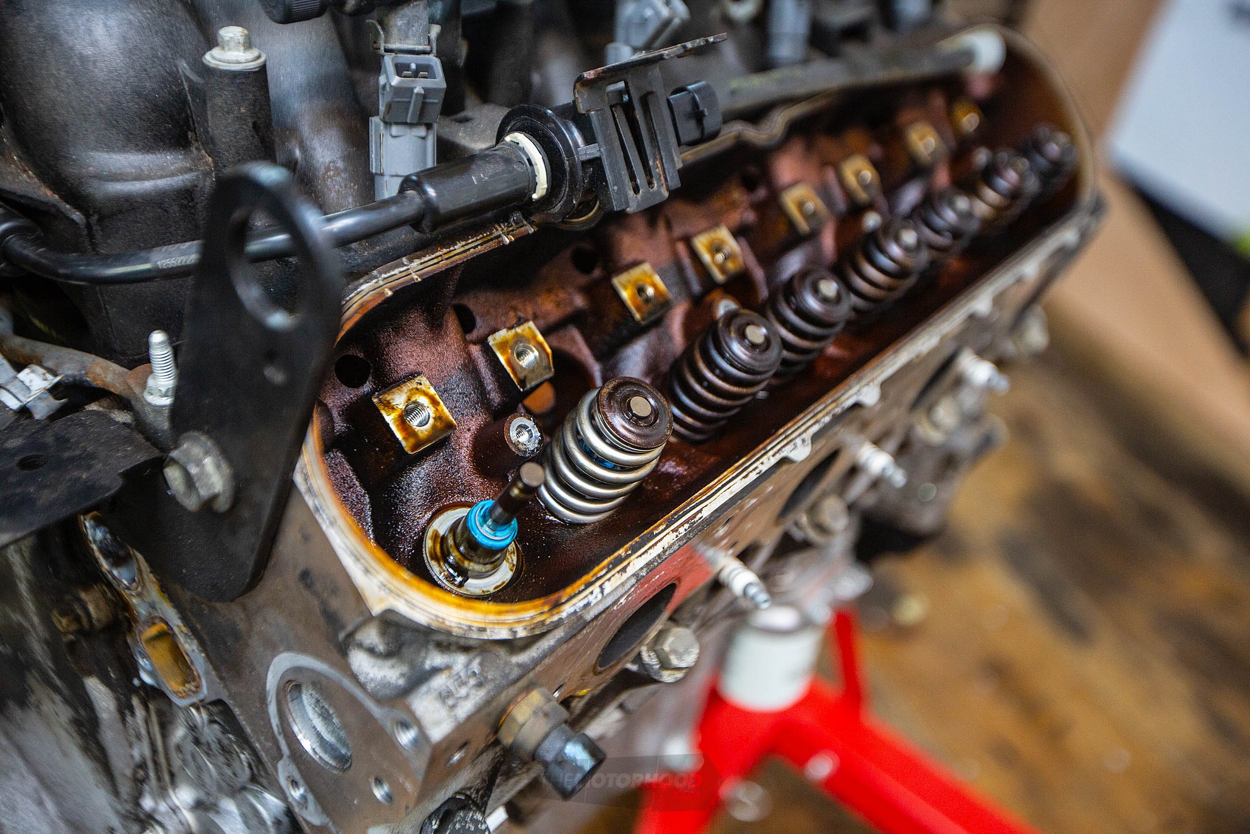
Now we move focus to the heads, first replacing the stem seals and then swapping out the springs for the recommended Beehives shown on the cam card. To do this you’re going to need some sort of spring compressor. There are plenty of options available online but we opted to make our own, as shown in the pull-out box: “Making a valve spring compressor”. This can also be made from a piece of steel plate if you wish.
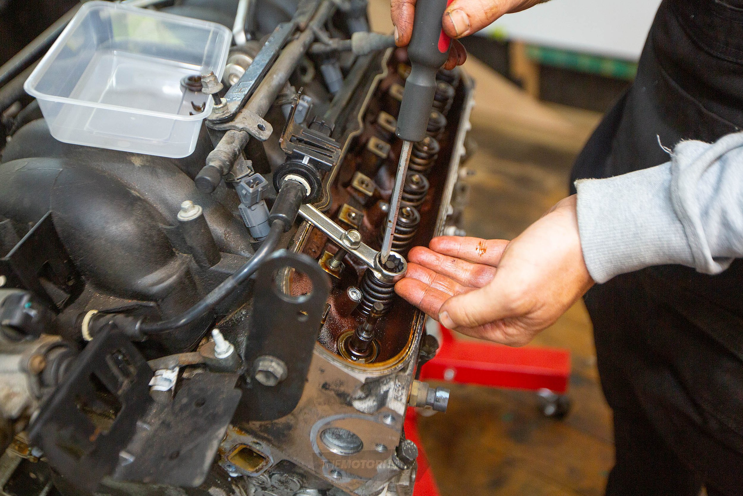
Step 17
You are also going to need to hold the valves up while swapping the springs. Using compressed air into the spark plug hole works well; we used the TDC method, rotating the engine until the piston we were working on was at TDC, which only allows the valves to drop a few mms. Work your way around the engine.
Step 18
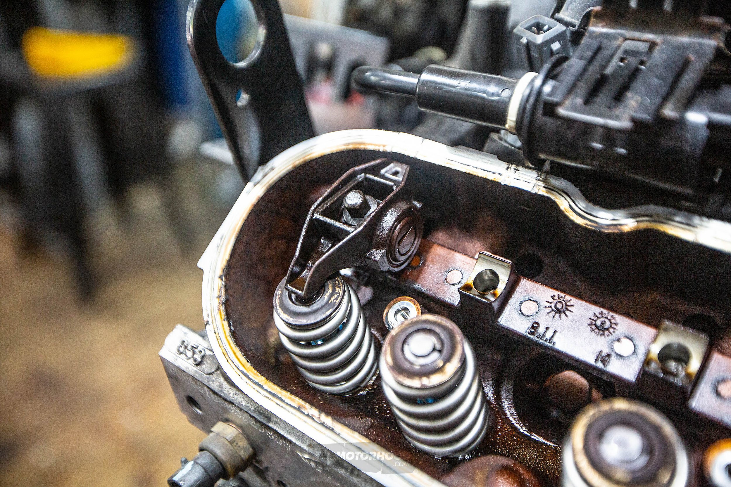
Now, you’ll need to check the pushrod length and then reinstall the rocker gear. Using a pushrod checker, with the cam on the base circle, the checker in place, and the rocker tightened down, you should be able to wriggle the rocker side to side a little, but not up and down. If you can shift up and down that means the rod is too short. Remove it, adjust the checker, and repeat the test until you can’t lift up the rocker. The measurement shown on the rod plus .040-inch is the correct length of your new pushrods. The extra .040 gives the correct preload.
Step 19
Once you have the new rods installed, torque the rockers down to 22 foot-pounds. Then complete the rest of the engine assembly. It’s worth noting that you will need to return the car to suit the new charm.
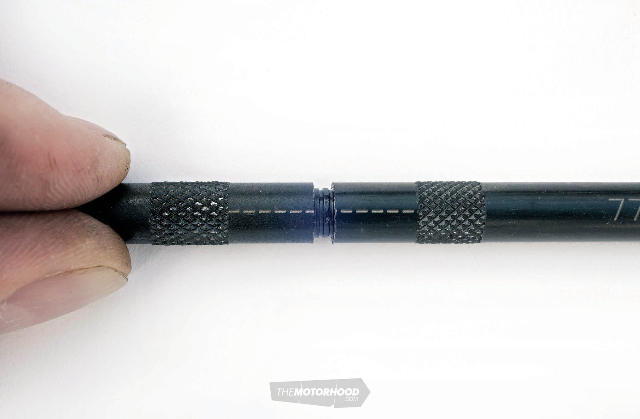
Making a TDC finder
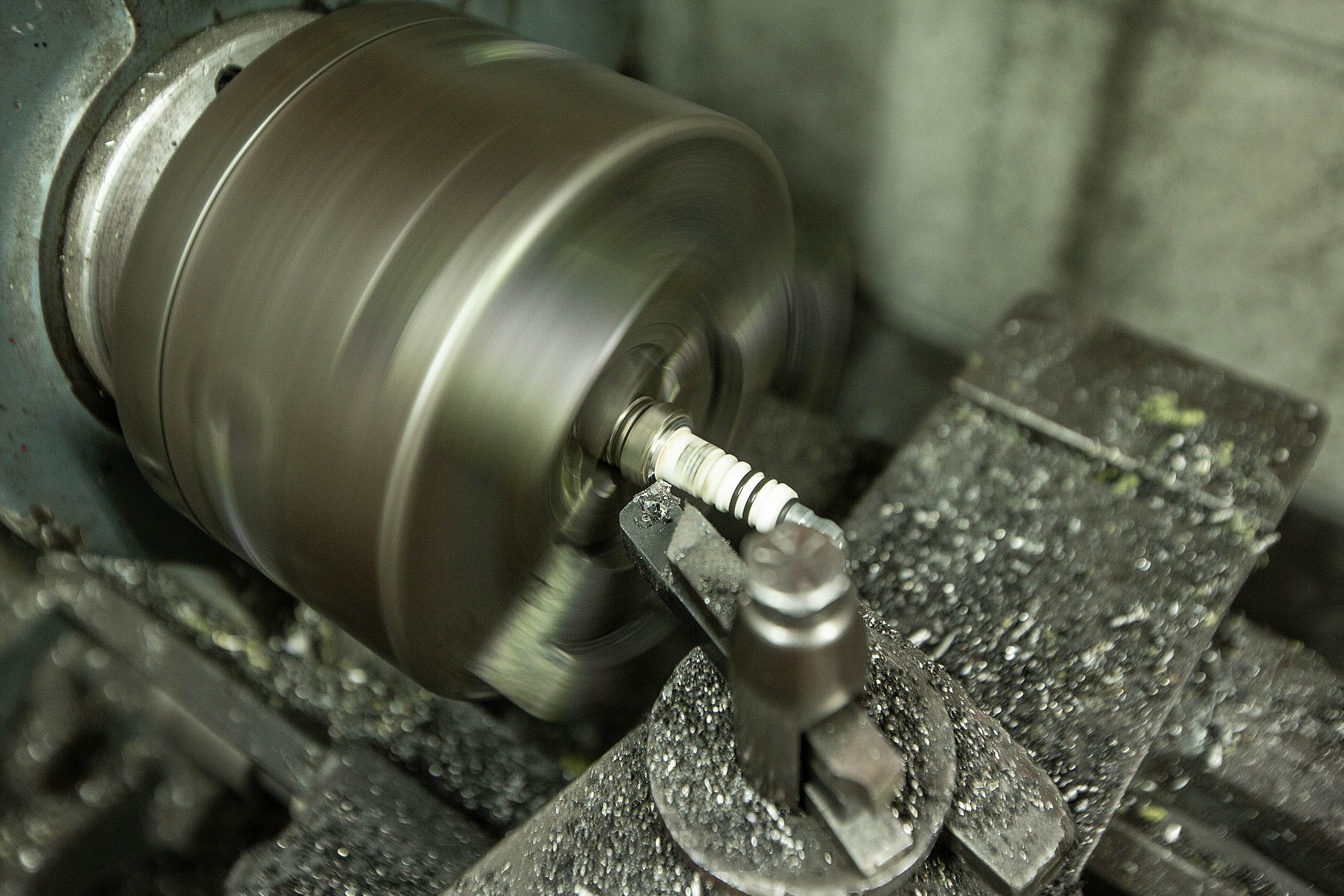
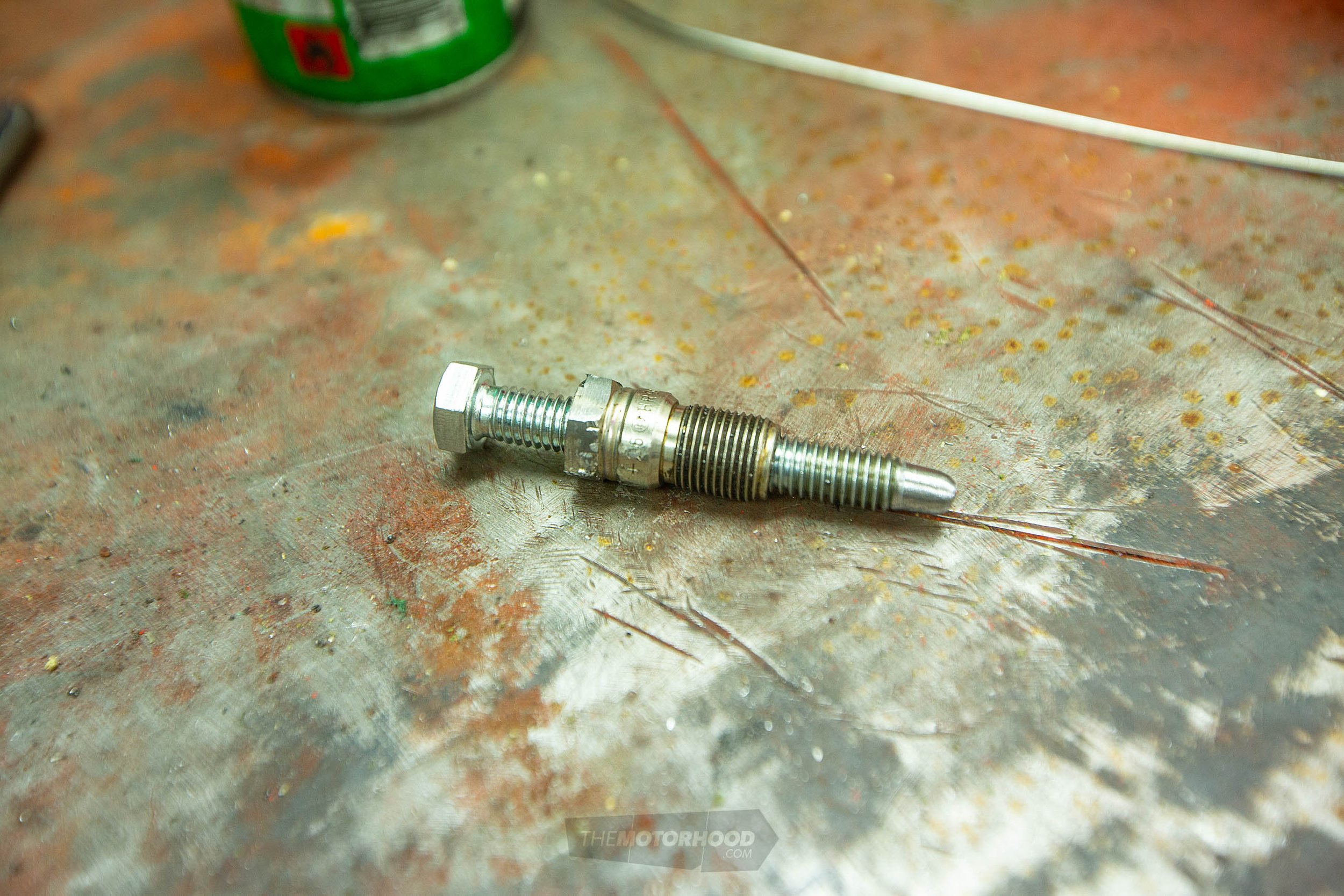
Yes, you can buy these. They are cheap, but getting one on the ground in New Zealand isn’t easy; the only one we found was $40 on Trade Me, and it had to ship out of Australia. Thankfully you can build one in five minutes with a few simple hand tools — the total cost was a couple bucks. Basically, you need to cut the electrode tip off, and then the small piece of rounded steel where the ceramic and steel meet. Don’t cut the nut off as you’ll still need this. Remove the ceramic from a plug with a hammer — yip, smash it out; it’s kind of hard to do. What you’re left with is the steel casing. Once you’ve removed it all, run a ⁵/₁₆ drill through, followed by a 3⁄₈ UNF tap. To make the probe, take a 3⁄₈ bolt and round the end so it won’t damage the top of the piston. Then thread together and you’re done.
Making a valve spring compressor
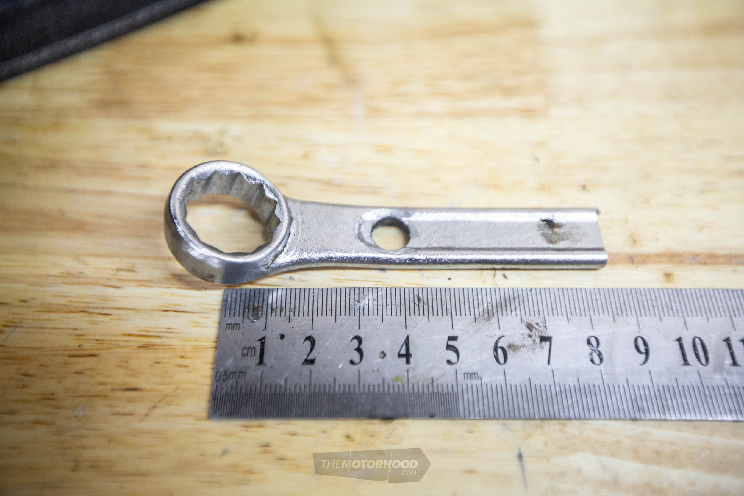
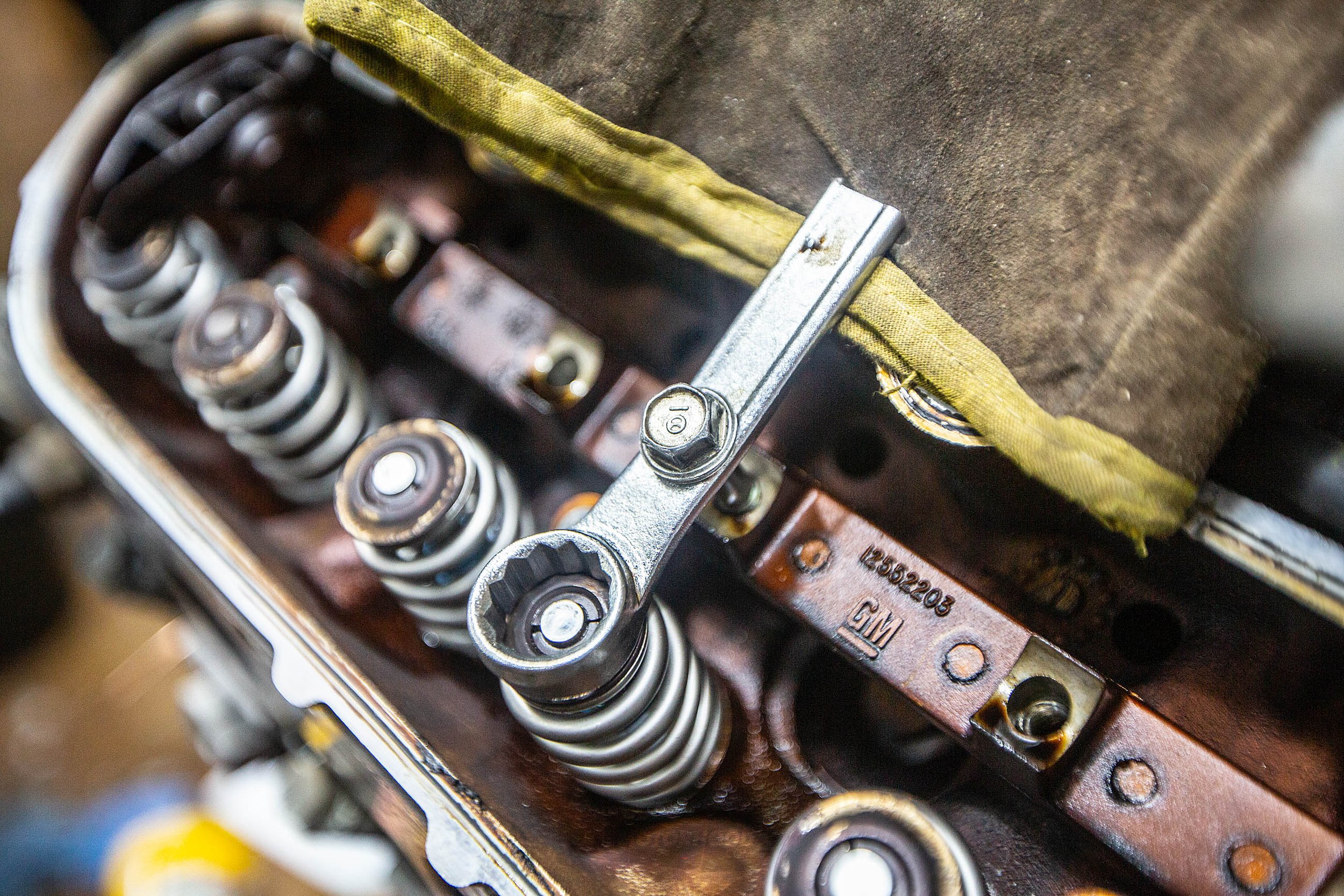
Like the TDC finder, you can buy these things from multiple suppliers and they are cheap. However, we wanted to show you a cheap way to do it at home with minimal tools, and, more important, minimal spend. You can make more elaborate versions, but this is the quickest and simplest way — we’re not planning on this job becoming regular. Take a ¾-inch or 17mm spanner and drill a 10mm hole 35mm from the end. You then need an 80mm-long M8 1.25 bolt, washer, and non-locking nut — a stud would be nicer but we couldn’t find one. This then bolts through the spanner and into the rocker stud, while the end rests on the edge of the head. We use a small piece of leather to remove the risk of damaging the sealing surface. Tighten the nut and it will compress the spring, allowing you to remove the two-piece retainer clip.
This article originally appeared in NZV8 issue No. 200